How the transmitter test port works?A majority of people knows for what purpose it is provided. But a greater per cent of them don’t know how it works. Let us clear this .
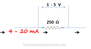
Process variables like pressure, temperature,flow etc is measured and transmitted to control system and monitoring stations . We know transmitters are widely used for this purpose .They measure process variables and transmitt in proper form so that the control panels will understand this signal . A major form used for transmission is two wire current loop .In this type process variables are sent as current output like 4-20 mA .A working supply of 24 V is given to through the same wire .see below figure .
Test port
See below image .The connection side of a transmitter is shown .
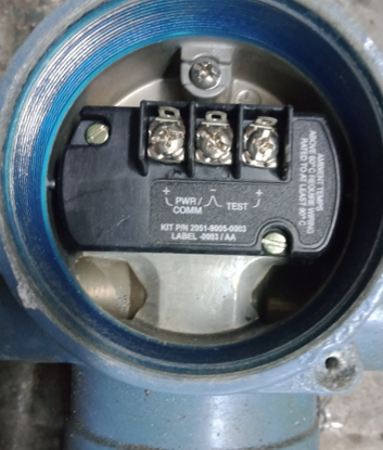
The power supply is fed to the positive and -ve terminals of the transmitter .So the loop is powered with 24 V and current signal 4-20 mA is flowing through the loop .We all know these things. See figure .
But have you noticed the terminals in transmitter .It has three terminals
+ Ve
– Ve
Test
We know the + Ve and – Ve for loop connections .The signal wires are connected to this terminals .Also transmitter is powered through the same terminal in two wire transmitter .So these terminals represents the terminals for +24 V and 0V .
What is the third terminal is for???
A major percent of people will answer this .
It is the Test port .Marked as Test
Yes .It is for the testing purposes .
If one want to check the milliamperes signal from the transmitter he can use this terminal .
Why Test port needed in transmitter?
why we need test Port?
We know current is always measured in series .And if the test port is not provided,one has to remove one wire from the terminal for some time .This is for connecting multimeter in series with the transmitter .And he has to connect the multimeter in series for current measurement .
.But one problem is there . While doing so, we are interrupting the loop or breaking the loop. It is not desired .Doing so may affect the process .So if you have another option ,it is better .For this case some manufacturers provide this test terminal for current measurement .we can measure current by hooking the multimeter in this test and – Ve terminals .And also we are doing this without any loop interruption .
So that’s it .A major problem in transmitter trouble shooting and checking online has been eliminated by the introduction of the test port ..But do you know how this circuit works???
May be a major percent will know for what this test port is for?
But a greater percent of them don’t know how this test port works!!!!
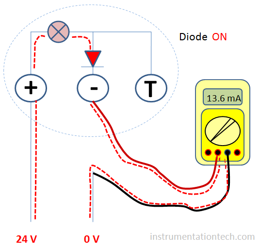
The following figure shows the circuit arrangement .Note the + Ve terminal of the transmitter leads to the internal circuit and exit through a diode to the – ve terminal .And the positive of the diode is shorted to the test port . See figure .
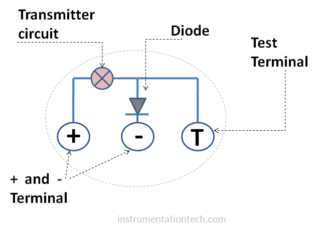

So In normal conditions ,nothing is connected to the test port .The current is pushed through the diode .The diode act as shorted link .It is forward biased and and even a small current is enough to drop a required voltage(knee voltage) across the diode to make it conduct .So the loop complete and current flows .
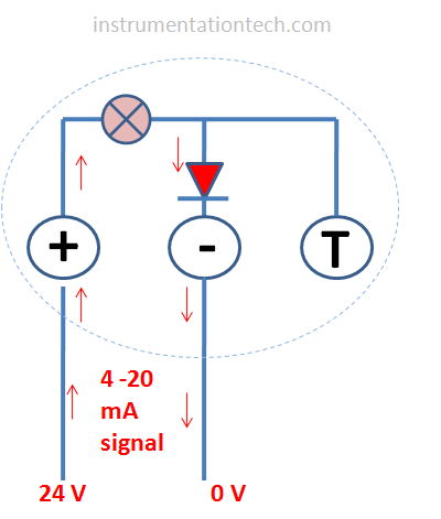
Case-1 Multimeter connected to +ve and - ve terminal
without using test port
In this case we need to remove one wire from terminal .This is for connecting multimeter in series for current measurement .In this case the diode turns on and allows the passage of mA signal .This is also the method for current measurement in series if test port is not provided .But one disadvantages is we are disturbing the loop or interrupting the signal . Because we need to break the loop for connecting testing device or multimeter . For connecting multimeter we should disconnect one wire of the loop from the terminal .And connect a multimeter in series .See below figure .
Measurement using test port
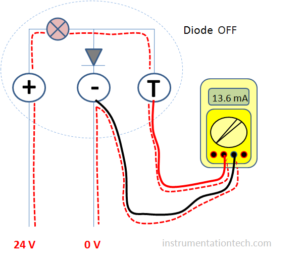
In measurement at the test port
Multimeter is connected to the test port and – ve terminal .No wire is removed?No
Is the multimeter is series ??
Multimeter showing current? Yes
But how???….
Ok .I will explain the concept .
When we connect the multimeter to the test and – Ve terminal,we actually bypassing the diode.See figure and note the current path .So the full amount of current will pass through this path .Not interrupting the loop .Not breaking the loop .This is because the impedance of the multimeter is very much less compared to the forward DC resistance offered by the diode .So the current takes easy path .Means a low resistance path .So the total amount of current flows through the test port when it is connected .Also the diode is not conducting . Because only a few amount of voltage is dropped across it .This is because the mA meter has very low impedance .Say 15 ohm .If 20 mA current passes through the multimeter ,then
Voltage drop V = IR
=( 20/1000 )×15
= 0.3 V which is far below the threshold value of 0.7 V for the silicone diode .So it remains in nonconducting state .And the whole current bypasses through the test terminal . At the same time the loop is live and the same amount of current flows through it .see figure .
Importance of multimeter impedence in measurement
Error may happen while checking through transmitter test port if we didn’t use proper multimeter .For example if the multimeter impedance is high enough to drop required voltage across diode..That is if the diode gets a voltage above its threshold voltage ,it turns on or conduct . This would cause the diode to pass the current when multimeter is connected to the test terminal . A part of current may flow through the diode under this conditions .So our meter only gets a part of current.And the measurement will become erroneous . So the multimeter or Milli ampere meter that we are using must be a low impedance one .
