Differential pressure transmitter calibration
DP transmitter calibration
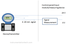
DP transmitter or differential pressure transmitter ,a popular instrument used widely in process control applications . Basically it is a device which compares two pressure values .And it generate a output equivalent to the difference in pressure .They are used in differential pressure,level,flow measurements . Calibration of DP transmitter is comparing it’s output and input with reference values using standard instruments with proper accuracy
. Dp transmitter Calibration:This article describes calibration of DP transmitter (two wire type 24 V DC power supply ,4-20 mA output.). Before that let us learn some basic terms .
General terms

Range
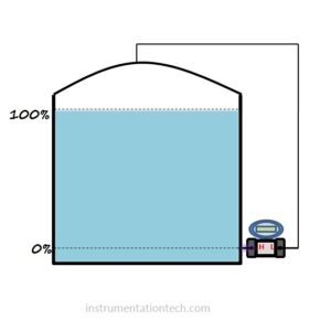
Range of DP transmitter is the differential pressure corresponds to the 0% and 100% of the process input respectively .
LRV
Lower range value .The lowest value of the calibrated range .This value corresponds to the 0% of the calibrated range .
URV
Upper range value.The highest value of the calibrated range.This value corresponds to the 100% of the calibrated range .
Calibration
We can calibrate a DP transmitter by applying the DP range . Applying Pressure corresponds to Lower range and upper range. (LRV and URV)to HP side of transmitter leaving LP side open to atmosphere. output current is adjusted to correct value (.4-20mA
Why we open LP port to atmosphere.????
we know differential pressure is the difference in pressure acting at high pressure port and low pressure port of the transmitter .
Or DP = HP-LP.so in order to calibrate a DP transmiter with a given DP range, we should create a differential pressure equal to the range values .And we know DP is the pressure difference between HP side and LP side .So we have to create a pressure difference equal to range values. This is easily accomplished by referencing LP side to zero and apply pressure in HP port,
.As DP=HP -LP
=HP- 0
=HP
So anything we given to HP port is the DP . provided LP is opened to atmosphere .So we only need to connect the pressure source to hp port only.
(Note: Here HP and LP is only to indicate the pressure applied on transmitter HP port and LP port. HP may not be always positive .It may be positive or negative depending on the conditions .)
Equipments and materials required for calibration
.1.24V power supply
2 Multimeter
3.Pressure source
5. High precision digital test gauge
6.Connecting wires
7.Tools.:screw driver, adjustable spanner
Calibration of DP transmitter with range 0-3000mmwc
Output 4-20mA
Power supply 24 V
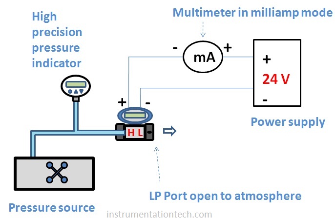
Calibration set up

Calibration procedure
1.Connect a pressure source to the HP port of the DP Transmitter leaving it’s LP port open to atmosphere .
2.Connect a High precision pressure indicator to the line . if the pressure source has an built pressure indication with sufficient accuracy then no need to connect additional reference indication .
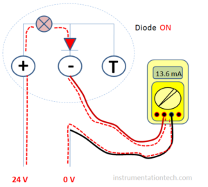
3.connect a 24 V power supply to the transmitter. connect a multimeter in series with the transmitter and power supply to measure the milliampere output .Ensure the multimeter probes are in correct slots and its selector is properly placed to measure milliampere .
4 .switch on the power supply and waits few seconds to stabilize the transmitter .
5.Apply a pressure equal to LRVvalue .In our case it is
0 mmwc .Check the output .It should be 4 mA . Adjust Zero if required .
5..Apply differential pressure equal to URV value.
3000 mmwc .Check the output.It should be 20mA . Adjust span if necessary .
6.Check for other input values .See below table
% . DP output
Input. mmwc. mA
0 % 0 4 mA
25%. 750 8mA
50%. 1500 12mA
75%. 2250 16 mA
100%. 3000 20 mA
Note
Note:Adjustments can be done through the provision given for zero span adjustment .It may be zero span button or zero span adjustment using front LCD display or it can be done through communicators like HART.
The calibration of modern transmitters is done through its front LCD display or using HART communicator .And calibration progam and sequence may varry with different manufacturers .


