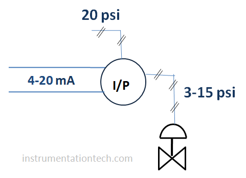
I/P converter or current to pressure converter is the device used to convert the electrical signal in to air pressure . It is mainly used for the operation of Pneumatically operated control valves .Most of the industrial applications use electrical type control signals . However final control elements like control valves (pneumatically operated) need air pressure for its actuation .In such situation it is essential to convert the signal in electrical form to corresponding pneumatic signal. And calibration of i/p converter also need to be done regularly for the correct outcome .
so these electrical signal is converted in to Pneumatic form in order to operate the pneumatically operated control valve .l/p converter will do this job .

See figure above .In I/P the input electrical signal is in voltage or current form such as 4-20 milliampere signal . And output is in Pressure form.Mostly used standard is 3-15 Psi output.Air pressure of 20 psi needed as a working supply pressure for the I/P .

To know how I/p converter woks see here I/P transducer working
calibration
I/P converter calibration
Calibration of I/P done by sourcing input milliamperes( 4-20mA)from a standard master device and compare the pneumatic output with a standard pressure receiving device .An output of 3-15 psi is expected corresponding to the 4-20mA input signal. Adjustments has to done to make the output same with the reference values .
Materials required for calibration of i,/p converter
I/P converter
Milliampre source or calibrator
Pressure calibrator or pressure source
Pressure indicating master device
Or
Digital pressure indicator with required accuracy .
Pressure regulator .
Tools required
Adjustable spanner
Screw driver
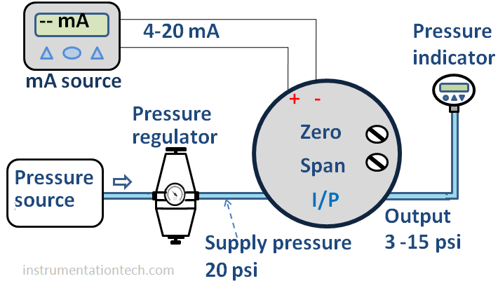
Calibration set up for l/p converter
1 .Connect a milliampere source to the input terminals of I/P
2 .Connect a supply pressure of 20 psi to the supply port of I/P. A pressure source with connected pressure regulator can be used for this purpose .Adjust the regulator output to 20psi .
3 .connect output port to a standard pressure indicating device through proper tubings and fittings .

Calibration
Apply 4 mA to the I/P .check output .It should be 3 psi . If not adjust the output to 3 psi using ‘ZERO’adjusting screw .
2.Apply 20mA . check output .It should be 15 psi.If not adjust the output to 15 psi by’ SPAN ‘adjusting screw.
repeat above steps 1 and 2 untill we are getting precisely 3 and15 psi corresponding to 4 and 20mA respectively .
3.check for the other points. As given by the below table.
Input Output
4 mA 3 psi
8 mA 6 psi
12 mA 9 psi
16 mA 12 psi
20 mA 15 psi