Two push buttons are wired to the PLC, one for start a motor and another for stop .We are using failsafe design .ie in field side START push button is connected in Normally open contact and STOP push button is connected in Normally close contact .Which one of the below logic works properly ???? logic 1 or logic 2??.How will you solve this ladder logic problem?
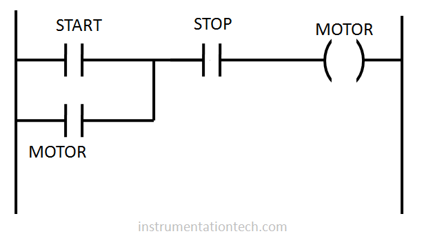
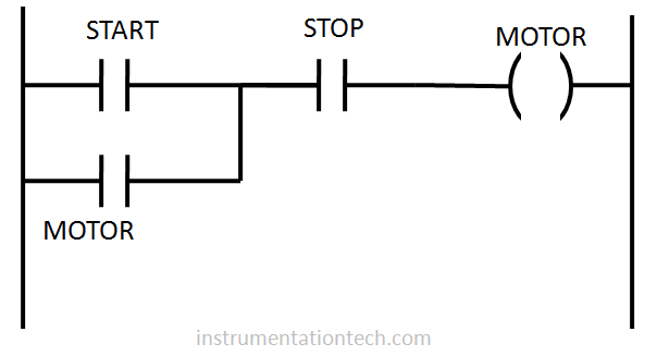
Program 1
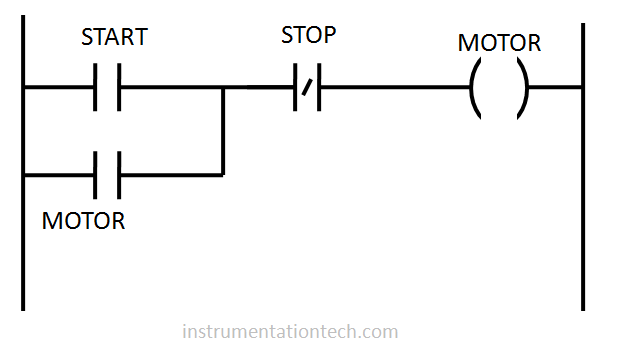
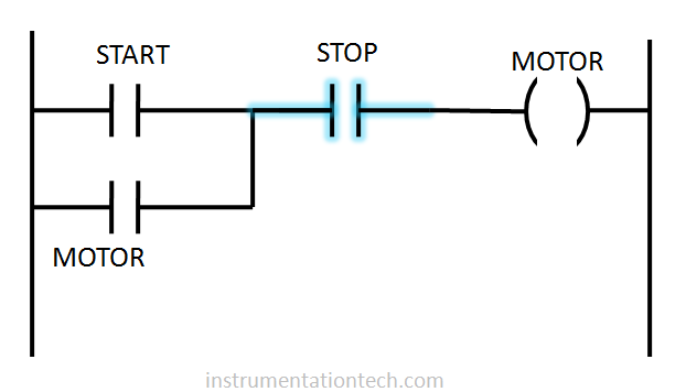
Program 2
The logic is so simple .But the fact is that most of the people gets the wrong answer for the above question.!!!!!!
So which one is correct ?
Program1 ? …,….or program 2?????
The correct answer is program1 !!!!!!!!!!!!!
Why the program 2 is wrong??
The only difference between program1 and program 2 is the program element for stop pushbutton is configured .It is configured as NC in ladder logic .And also at field it is wired to NC . What’s wrong with that????
So that is the misconcept .To understand what gone wrong you should understand the fundamentals related to NO and NC program elements in PLC. and their changes of status with the real world signal.
PLC input status 0 and 1 according to the real world signal
Real world status 0 and 1
Suppose we have an input wired to PLC . For example a push button.So this push button feed or cut power to the input terminals as per the status of its contact.The status of its contact changes when it is pressed or activated .Anyways the input channel of PLC or control system either receive a voltage or no voltage according to the state of input device.In this case push button .
So remember
No power to the input channel …………. 0
Power to the input channel …………….. 1
So if the input signal wires is connected in Normally open contact of push button,then PLC reads ,
1 when push button is pressed (activated)
0 when not pressed (normal condition ) .
Also if the input signal wires are connected in Normally close contact of push button,then PLC reads ,
0 when NC pushbutton is pressed
1 when it is not pressed (normal condition)
So that is the case for the real world signal. Or how PLC reads a real world signal .The implementation of the ladder program in PLC is done through different types of program elements like NO contacts ,NC contacts ,Timers, Counters etc .Proper combination of these elements in the program represents the control philosophy or the logic .One need to understand the nature of each program elements in its normal state and activated state . otherwise error may happen in program development.
.Let us take our example .We are using only NO and NC contact elements in ladder logic program .One important thing we always need to remember is the real world signal and the program elements are not the same . program elements are the representation of the real world status .And one more thing there may be different program elements assigned for a single input .
.For example just take a case where a push button with NC wired to the PLC .
How we represent the push button in ladder program .?????
With a NC program element??? or with NO element ??
The answer is you can use any of them .You can use both of them .You can use them many number of times in different places .!!!!!
So it is just like a relay but with many contacts .
Also it is necessary to understand the status of the program elements according to the status of the signal .Let us learn with our case .
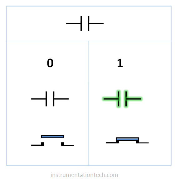
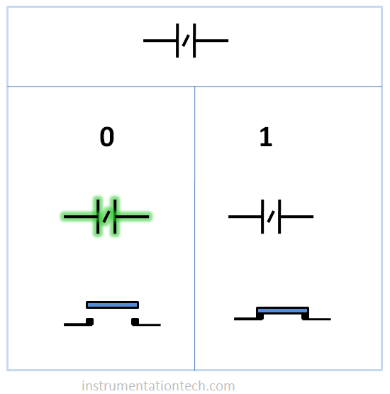
In ladder logic program a zero input status makes the program elements NO and NC to stay it’s normal condition.ie NO contact remains open and doesn’t conduct and NC contact remain close and conduct .
A ‘1’ input status makes the program elements in it’s activated condition .ie NO contact closed and conducts .and NC contact opens and doesn’t conduct .The conductive state or logical continuity is usually highlighted in PLC programs to know the real world status online.see below figures .
states of NO element in a ladder program
states of NC element in a ladder program
So back in to our problem.Let us examine the two cases separately
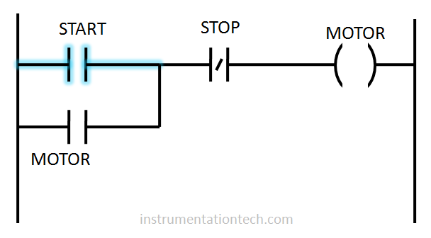
Ladder logic 1 see below figure.
When start and stop pushbutton is not pressed .The see below figure .
The input status of START pushbutton has a status of 0 as it is connected to the normally open contact(in field side) .and no power is fed to the input channel when it is not pressed .And NO contact assigned for the PLC program remains open as it is receiving a ‘0’ .
The input status of STOP push button has a status of 1 as it is connected to the normally close contact in field side and power is fed to the input channel when it is not pressed .So NO contact assigned in PLC program for STOP push button stays at close as long it is in normal condition or not pressed condition .see figure below .
When START pushbutton pressed
Pressing the START button cause the input status of START pushbutton changes to’ 1′.This cause causingthe NO contact in ladder logic to change its status to close . the output coil address for motor get on or changes to a status of ‘1’ from ‘0’ . .see below figure .The motor turned to on.
Releasing the START pushbutton doesn’t cause the output coil to de energize because a NO contact is programmed parallel with the START contact.This contact has the same address as that of output coil..Whenver output coil energizes by pressing START pushbutton, this NO contact also closes as it has the same address as that of output coil . When START is released , logical continuity for the rung is maintained by this contact .So motor continues in ON condition .see figure .
STOP
When pressed the STOP push button the contact opens once causing the latching function to inactive .Logical continuity is disturbed causing the output coil for motor to de energize .Motor turns to off .
After this the program looks like that is shown below . Another Start initiation is needed for starting the motor .
case2
Let us take the second ladder program .This program will not work as desired with the given field wiring configuration .
Why???
You can explain as you have already gone through the concept.
Yesss!!!!
The program doesn’t works or it is not suitable for the given field wiring .This is because the STOP push button is wired in NC in field .And it always send power to the PLC terminal when it is not activated .Or PLC reads 1 for the STOP input when the button is not pressed . The program element for the STOP in ladder program is a NC element .And it doesn’t conduct when it receives 1 .So the motor will not start because logical continuity is not established .
So the program no 1 is the correct program for the given field wiring configuration .
And one more thing . program 2 will work if we modify the field side .That is if we connected the STOP signal to a NO push button .In such case the program 2 works .But it is not recommended to connect the STOP signal to NO contact of push button .This is because such cases will not ensure a failsafe character to the signal loop .